Network Admin Guide Tutorial
This document includes network issues across OSI Layers (L1–L7) with explanations and solutions supported by simulations.
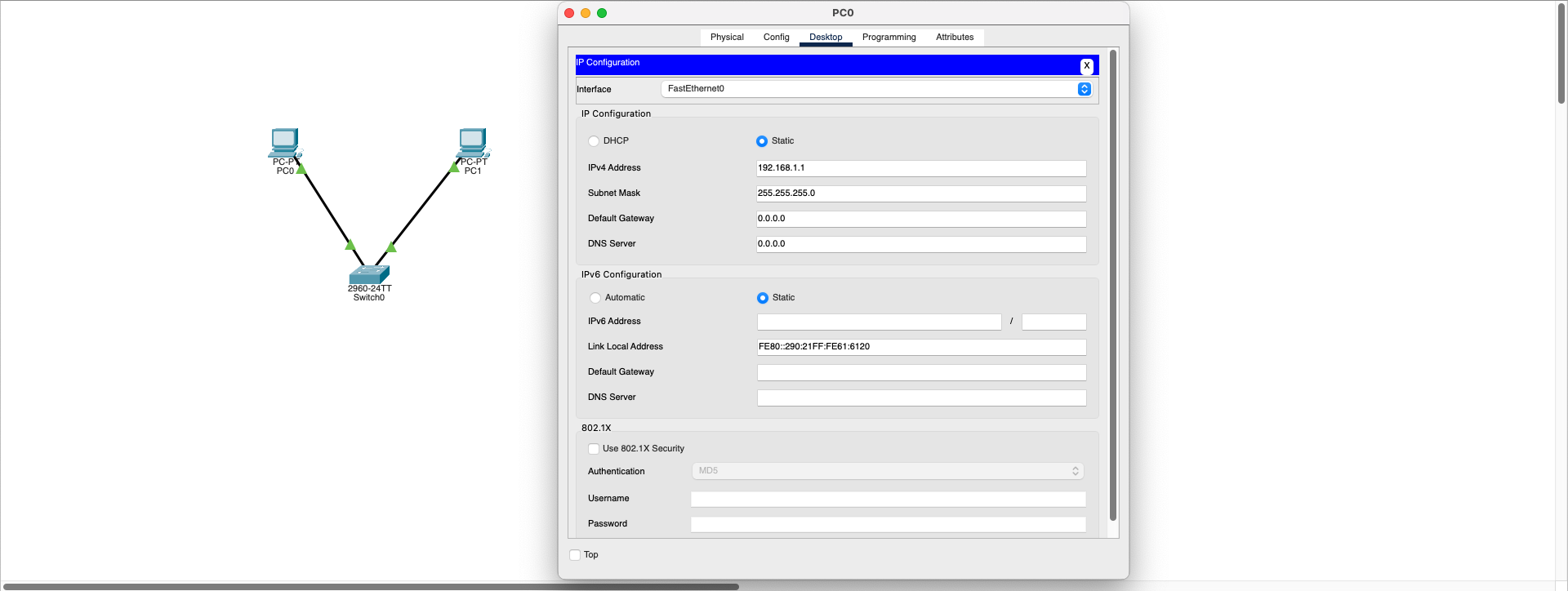
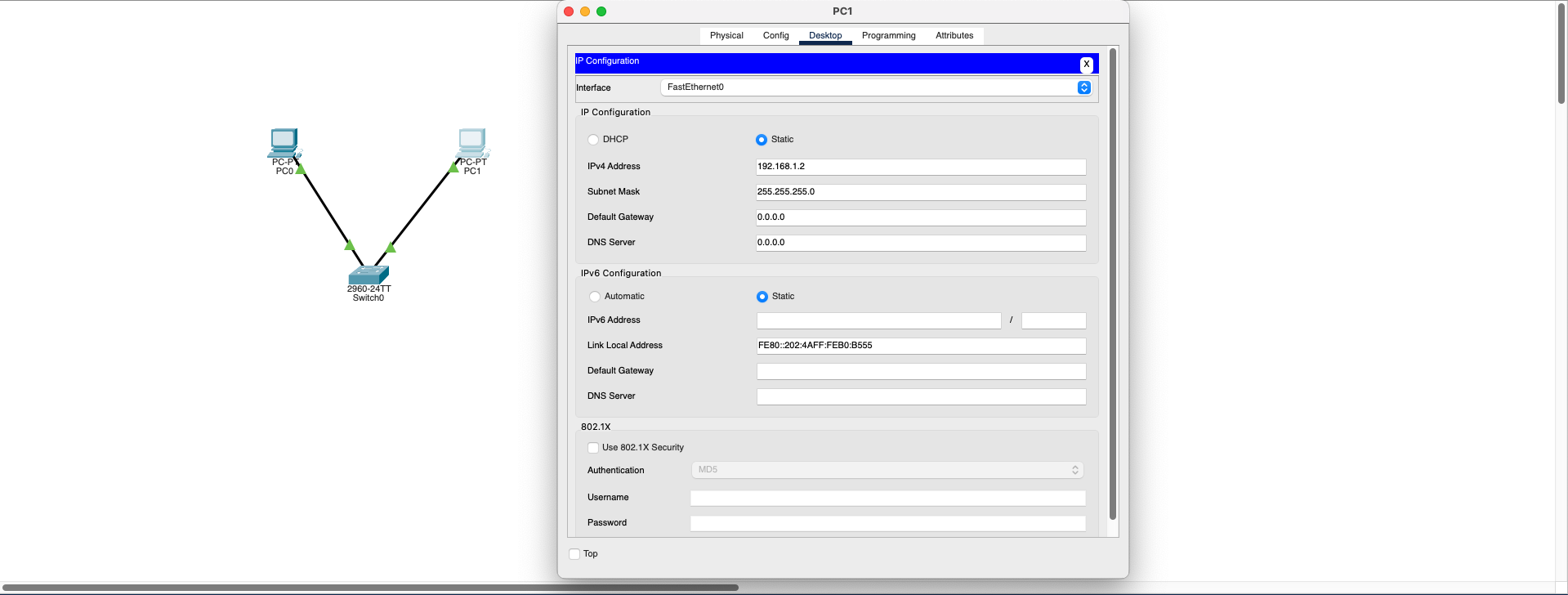
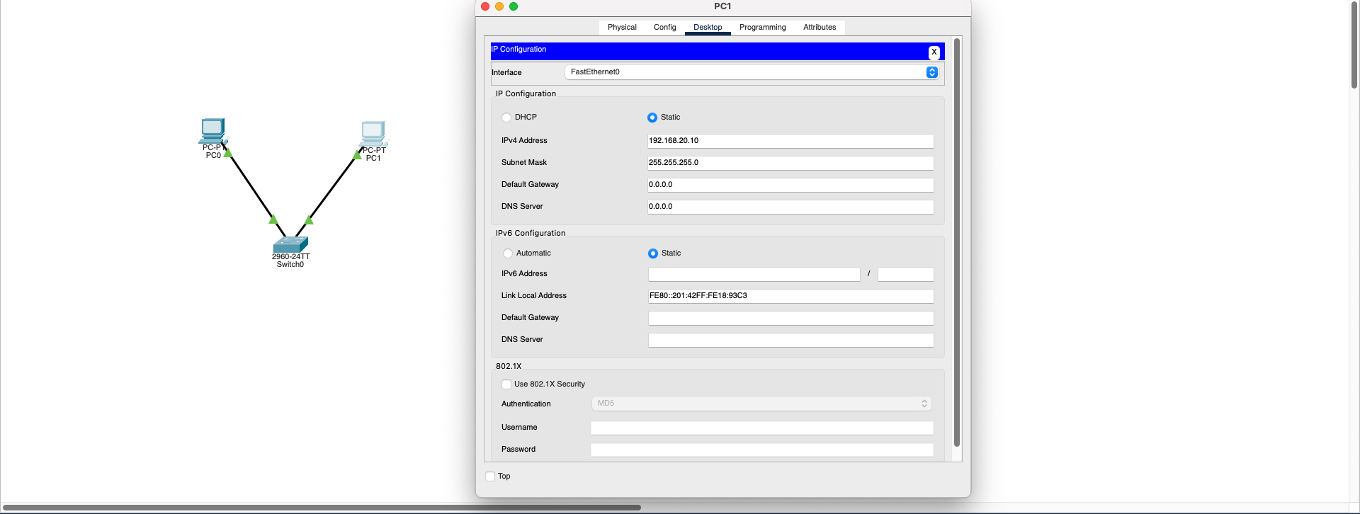
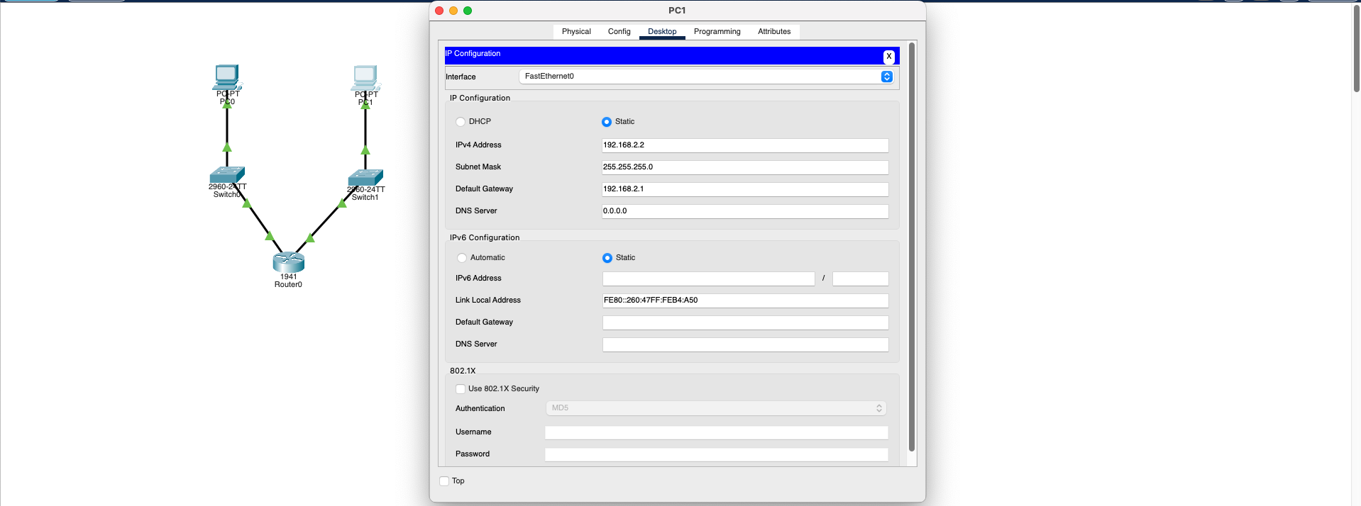
IP Conflict (IP Collision)
Network Layer (L3)Symptoms:
- In some cases, "Duplicate IP Address Detected" warning may be visible
- Network connection is lost or becomes unstable
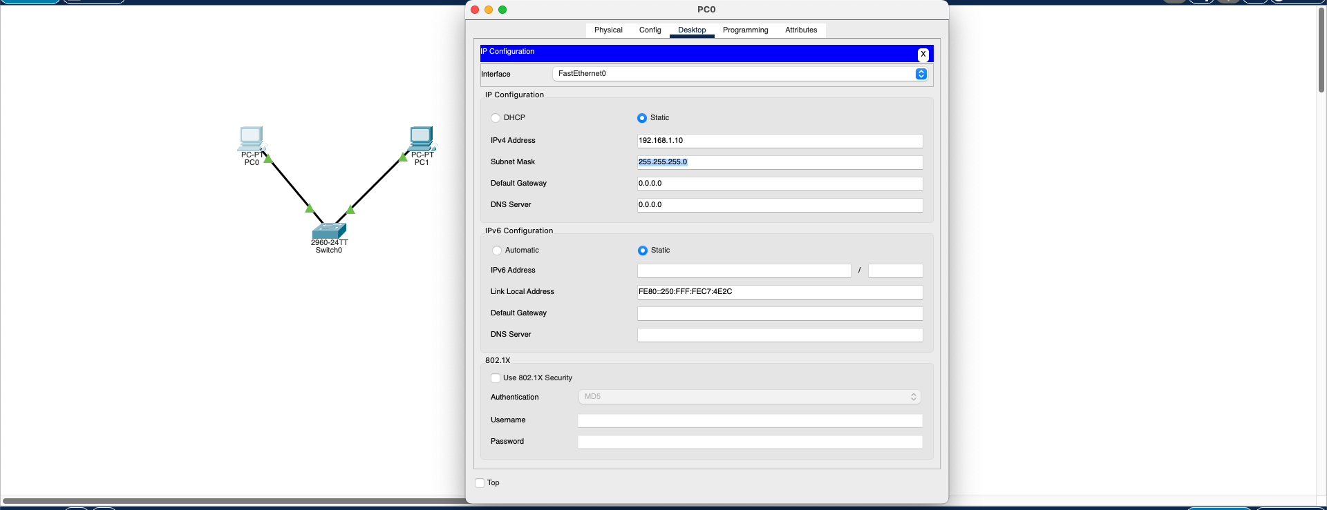
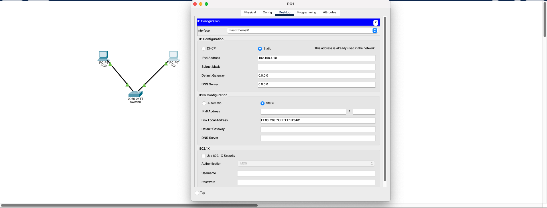
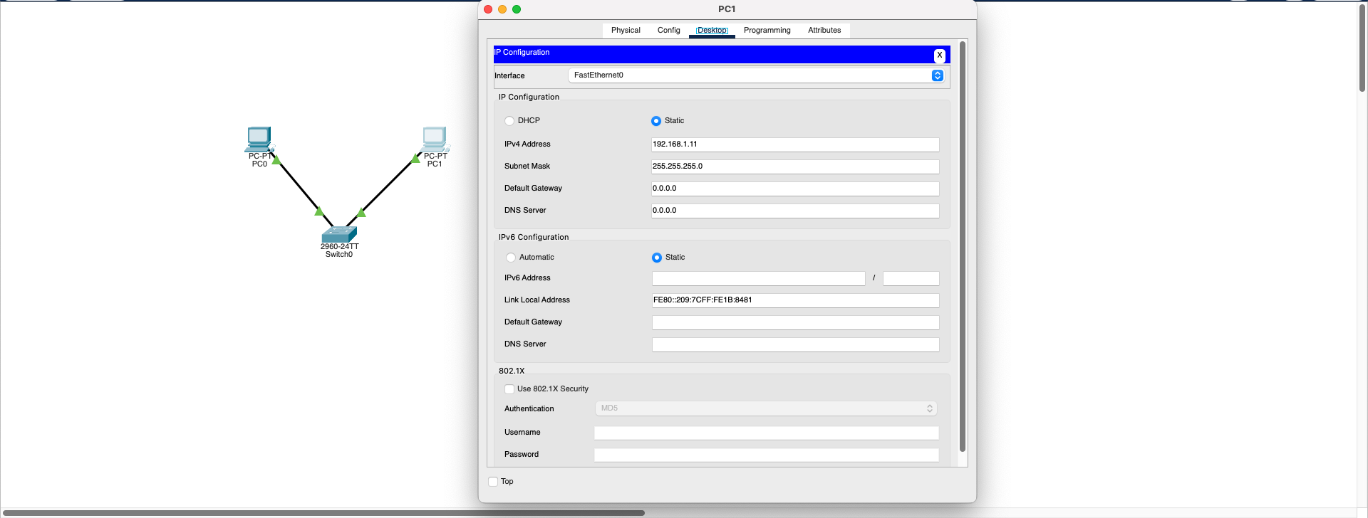
- Assign a unique IP address to each device
- IP addresses should be distributed in a planned manner or assigned automatically using DHCP
- Verify that each device has a different IP address in the same subnet
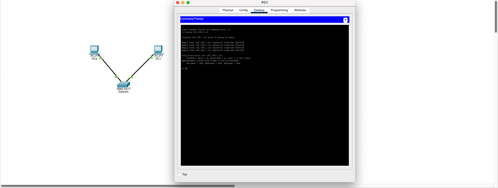
Result: IP conflicts are Layer 3 (Network Layer) problems that prevent proper routing and communication between devices. With unique IP assignment, network communication is restored and devices can communicate successfully.
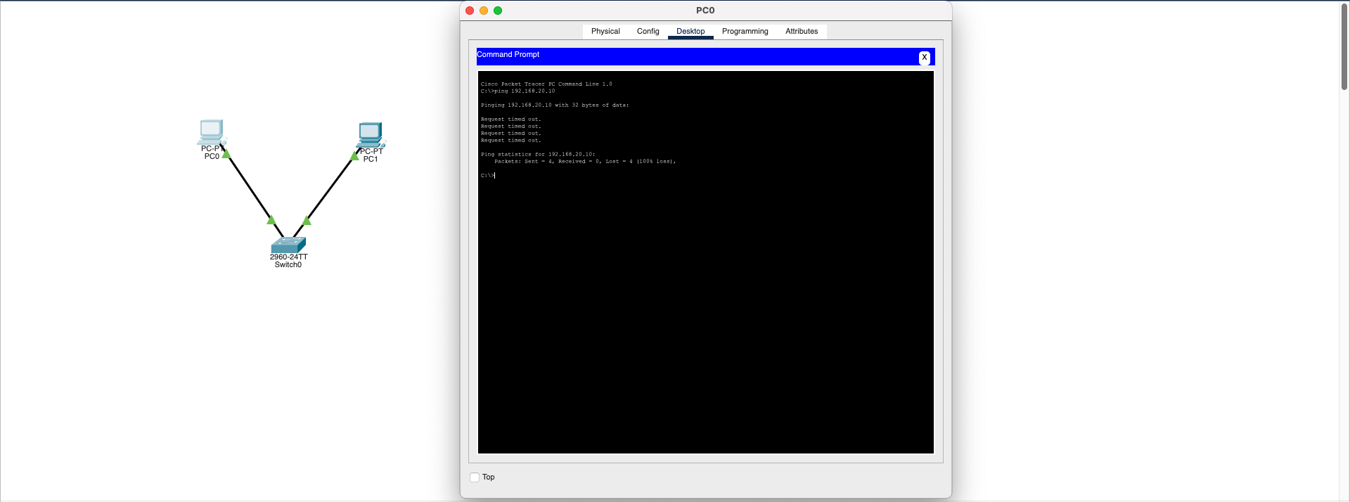
Download SimulationMAC Address Conflict (MAC Address Collision)
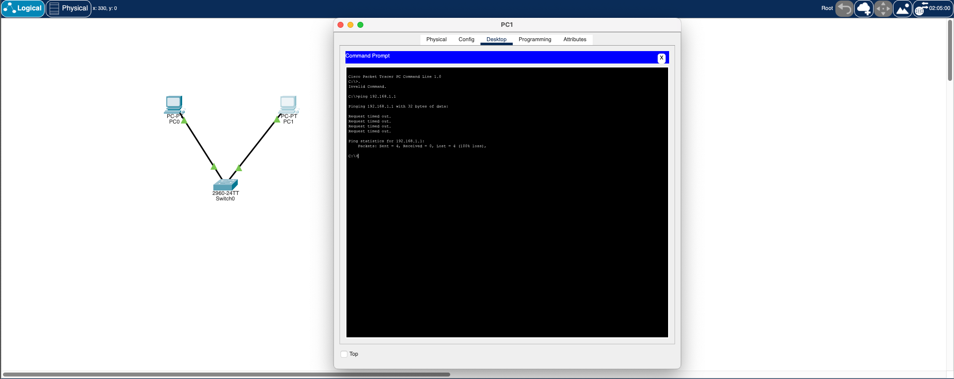
Data Link Layer (L2)Symptoms:
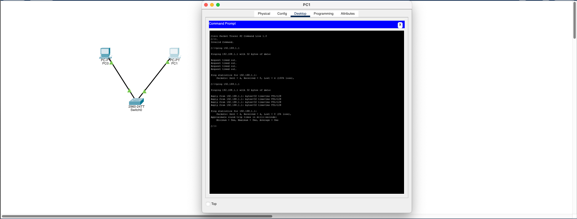
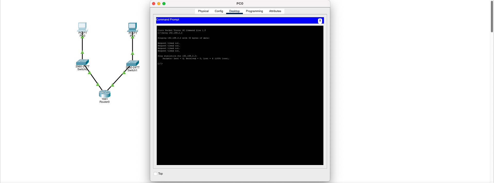
- Ping command yields no results (Request timed out)
- Network performance decreases
- ARP tables get confused
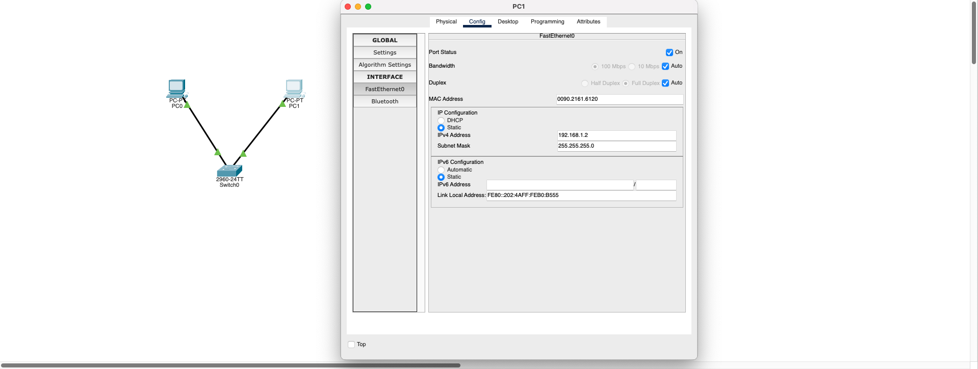
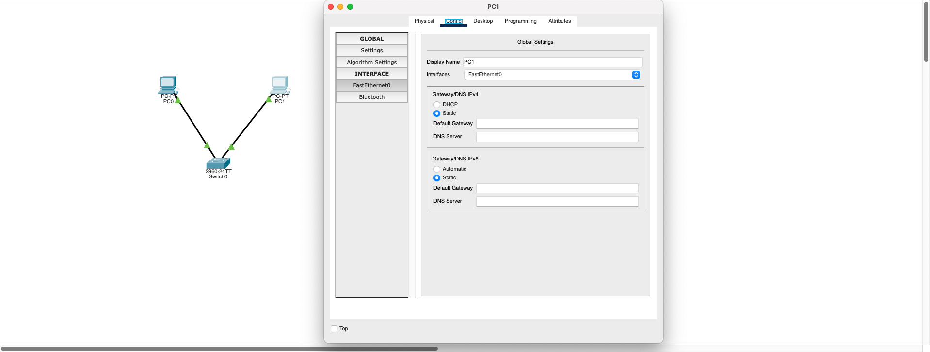
Each device must have a unique MAC address.
Solution Steps:
- Go to PC1 →
Config > FastEthernet - Change the MAC address (for example, enter a different value like 00D0.BA1D.1C02)
- Repeat the ping test
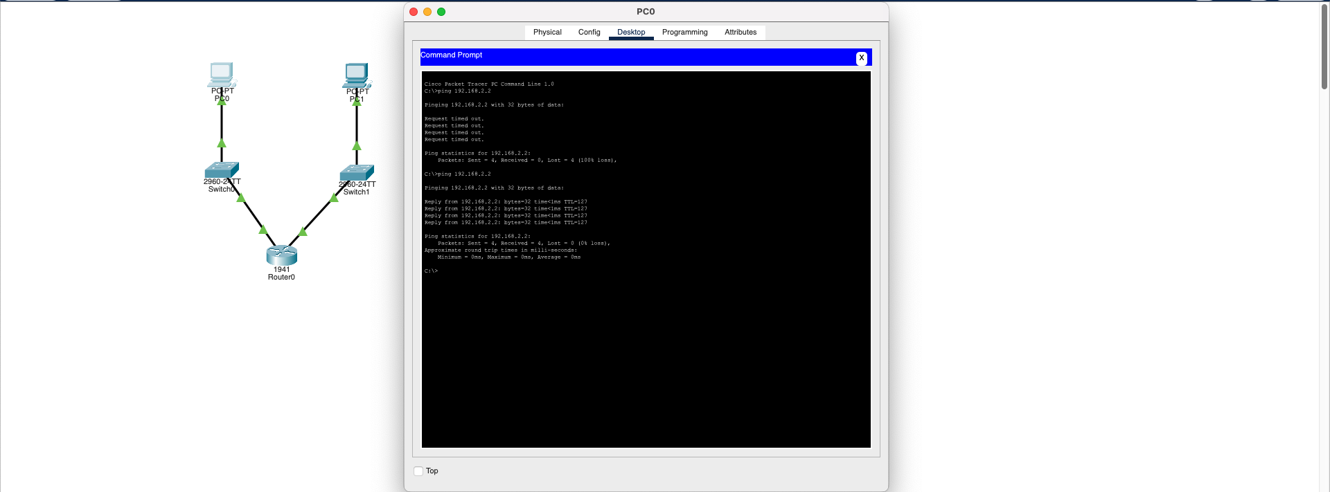
Result:
- Ping becomes successful
- Switch MAC table works properly
- Network instability is eliminated
Technical Note: This is a Layer 2 (Data Link Layer) problem. MAC addresses are used for frame switching within the local network, and conflicts prevent proper frame delivery.
Download SimulationVLAN Misconfiguration (VLAN Wrong Configuration)
Data Link Layer (L2)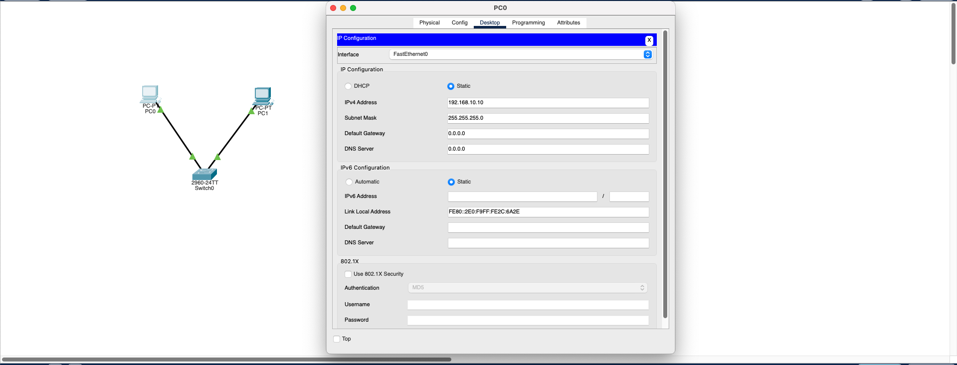
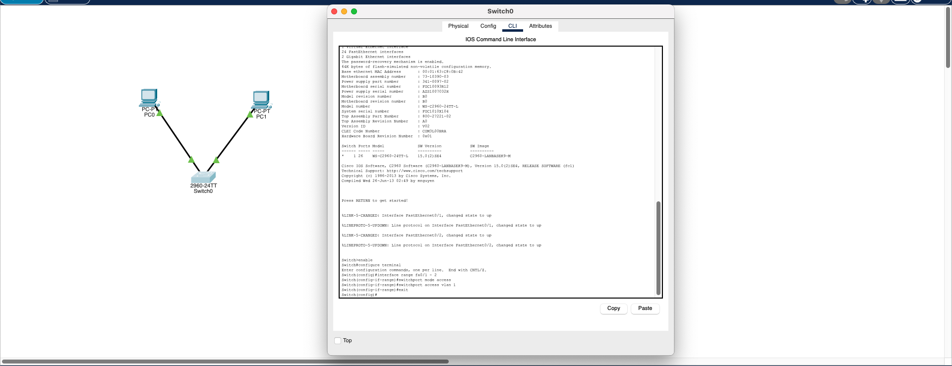
🔧 Step 1: Create Correct VLANs
                            Switch(config)# vlan 10

                            Switch(config)# vlan 20
🔧 Step 2: Assign Ports to Appropriate VLANs
                            Switch(config)# interface fa0/1

                            Switch(config-if)# switchport mode access

                            Switch(config-if)# switchport access vlan 10


                            Switch(config)# interface fa0/2

                            Switch(config-if)# switchport mode access

                            Switch(config-if)# switchport access vlan 20
🔧 Step 3: Add Routing If Needed
If communication between VLAN 10 and VLAN 20 is desired, Router-on-a-Stick or Layer 3 Switch routing configuration is required.
Result: The main cause of this problem is incorrect configuration of logical separation (VLAN/subnet) despite correct physical connections. Although this problem appears at Layer 2 level, it also has Layer 3 effects. With proper VLAN assignment, network segmentation is achieved and communication is re-established.
Download SimulationCable Fault
Physical Layer (L1)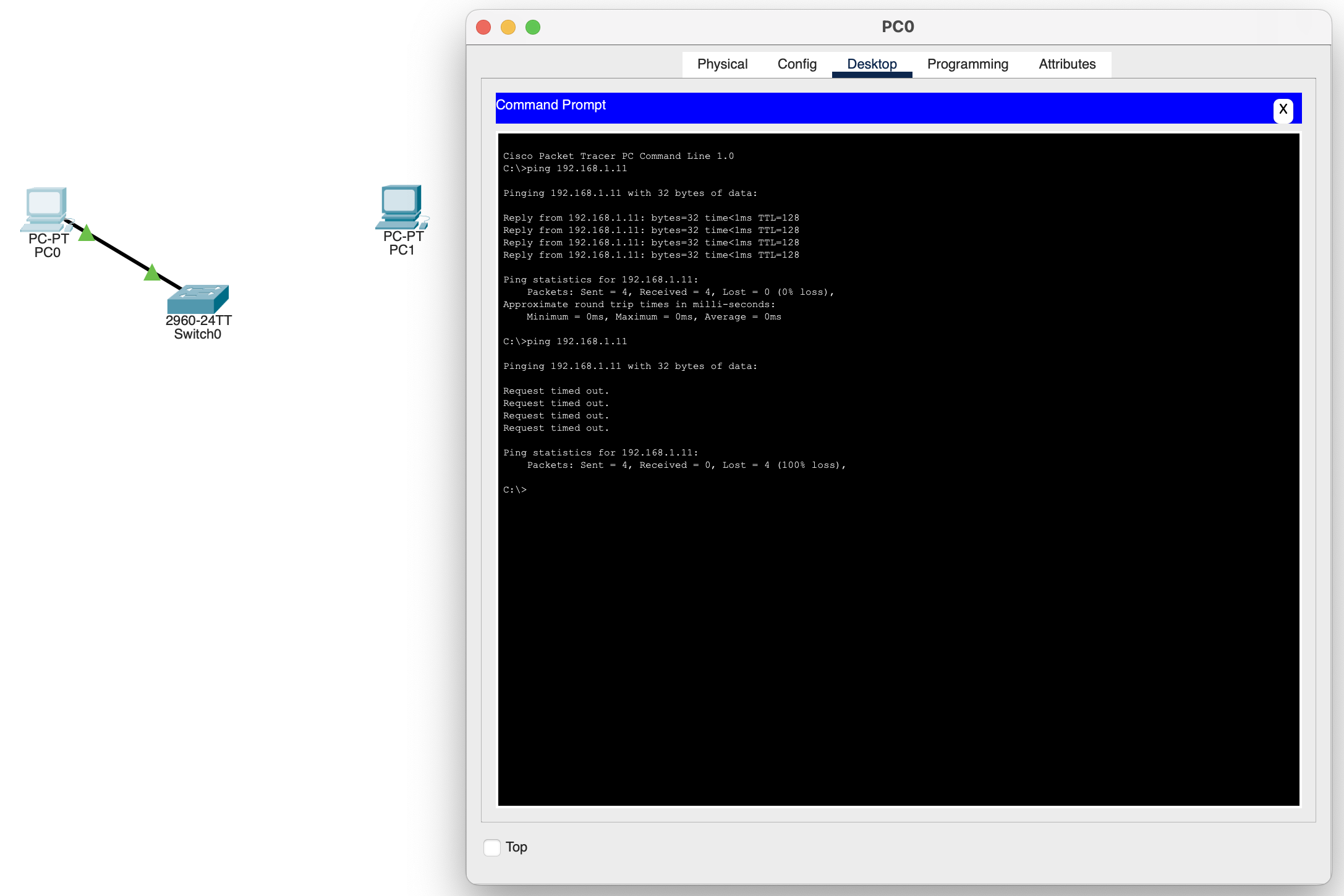
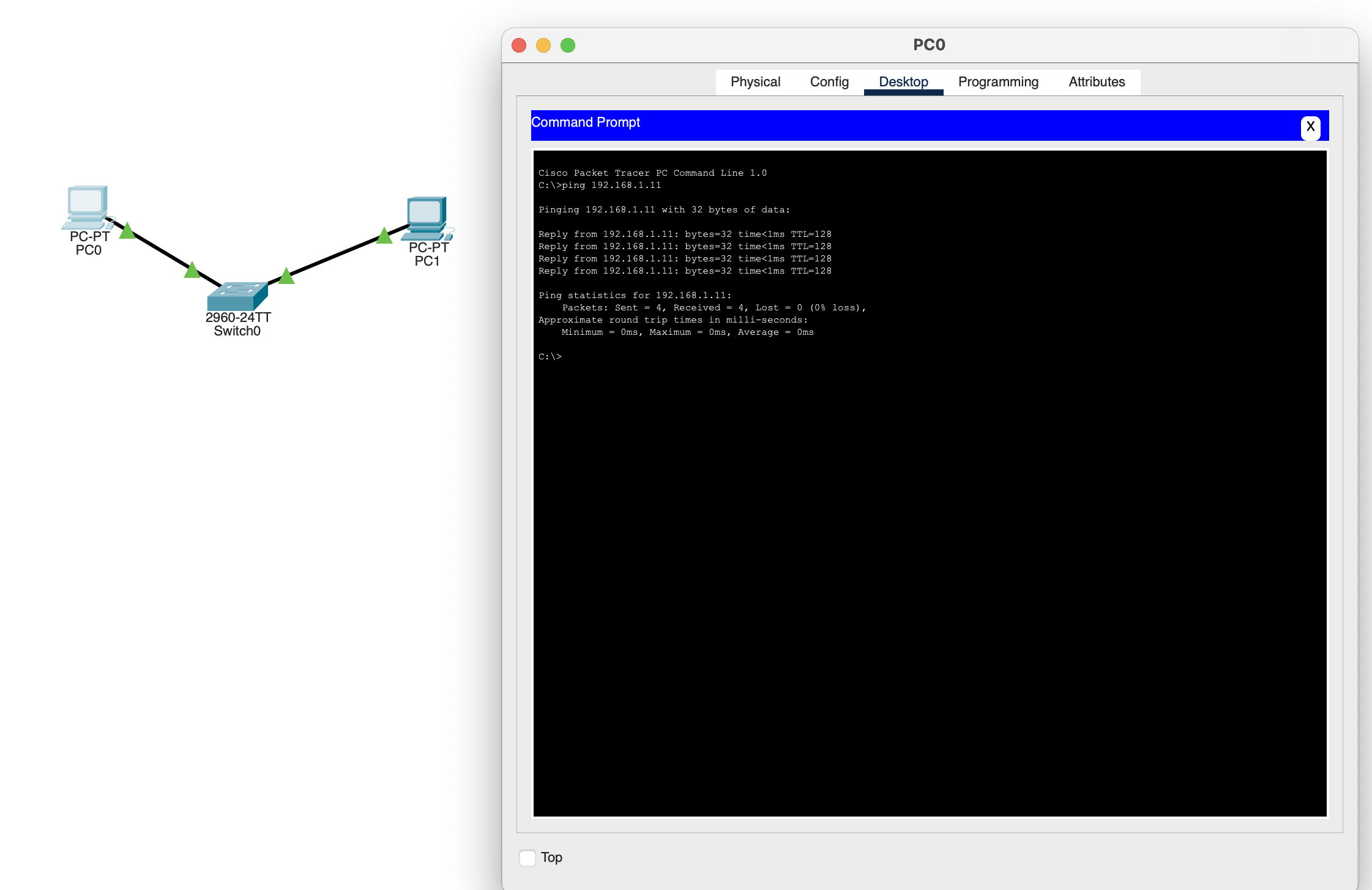
Diagnose the physical connection and restore the faulty cable. Use cable testers to verify cable integrity. Check link lights to confirm connection status.
Download SimulationDefault Gateway Missing
Network Layer (L3)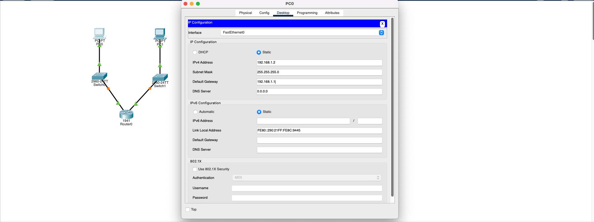
Configure Default Gateway: PC2 must be configured with the correct Default Gateway address (192.168.2.1 - the router's interface on PC2's side). Once configured:
- PC2 correctly forwards packets to the router
- Router forwards packets to the other network
- Ping operation completes successfully
- Inter-VLAN routing works properly
Technical Note: This is a Network Layer (L3) issue. IP routing fails because the exit point (router IP) is not defined for routing decisions.
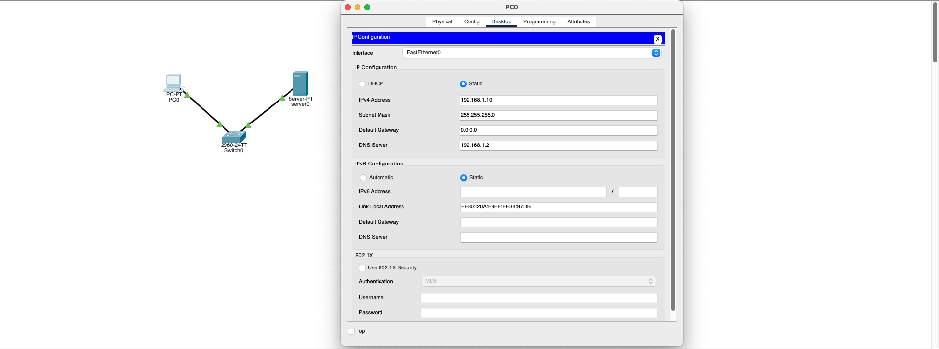
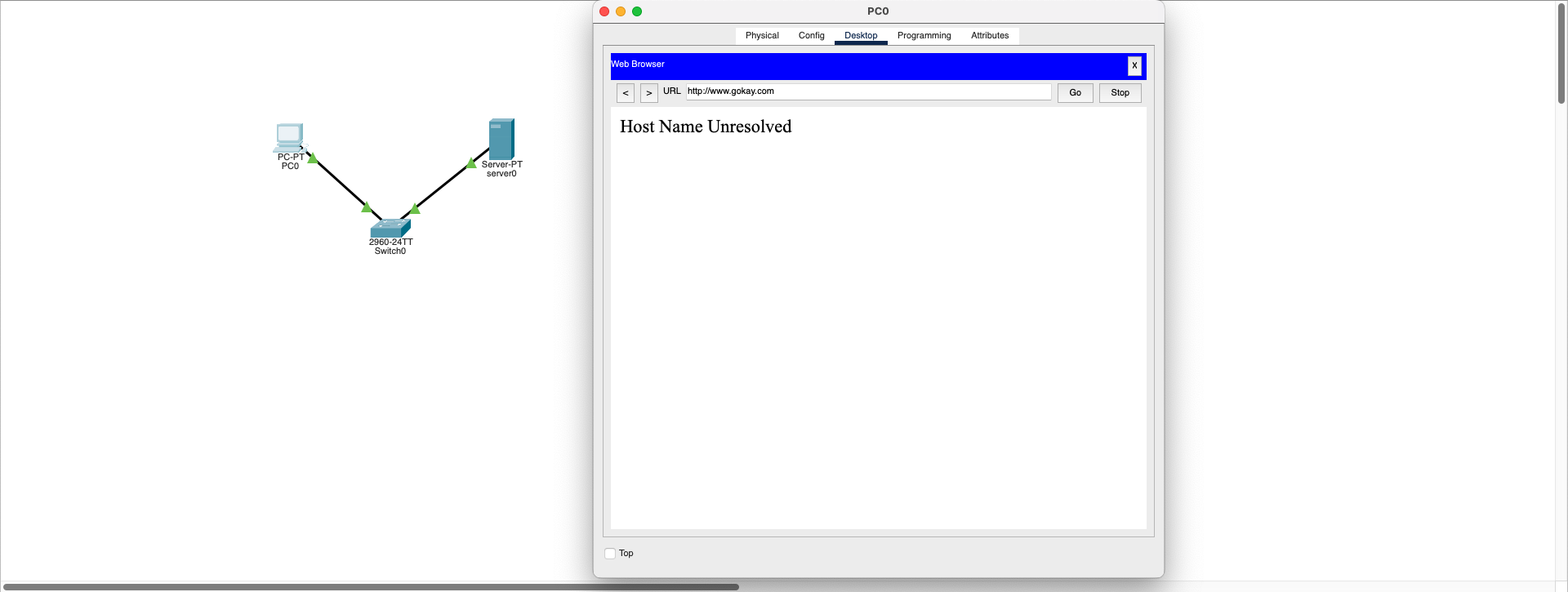
Download SimulationDNS Server Unreachable
Application Layer (L7)- Client device's DNS address may be incorrectly defined
- DNS server is not configured or the service is not active
- DNS record (domain name → IP mapping) is missing
- No connection between server and client
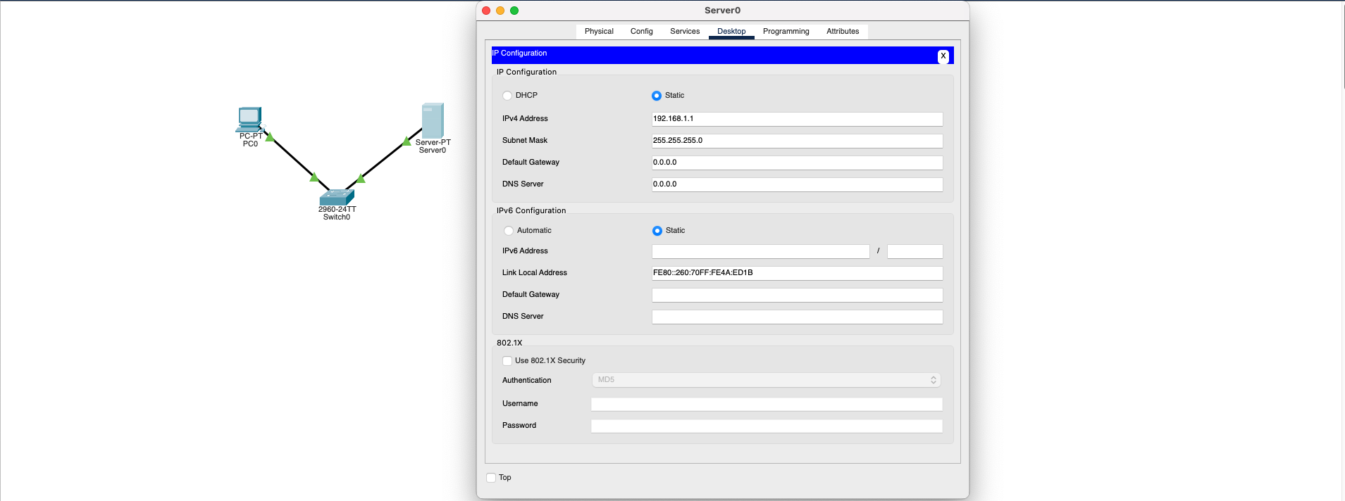
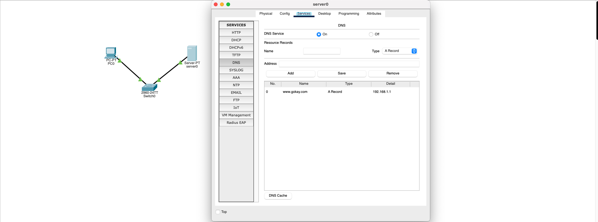
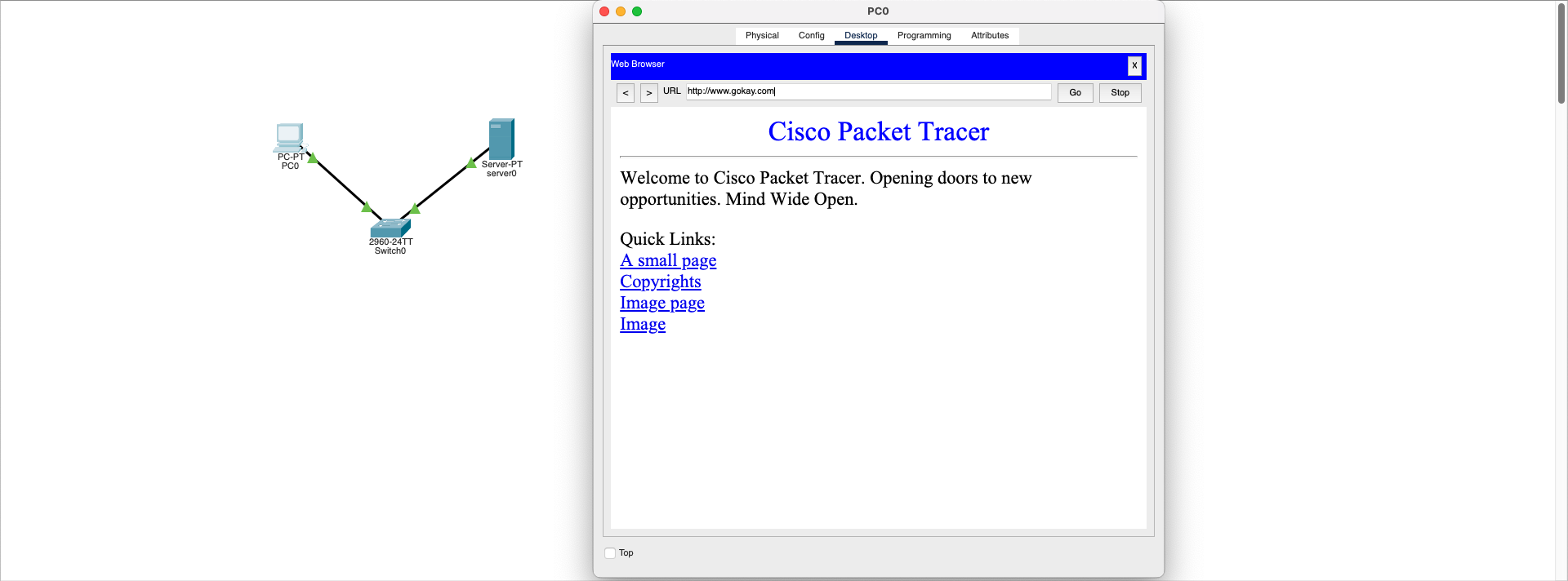
To solve the problem, the following basic points should be checked:
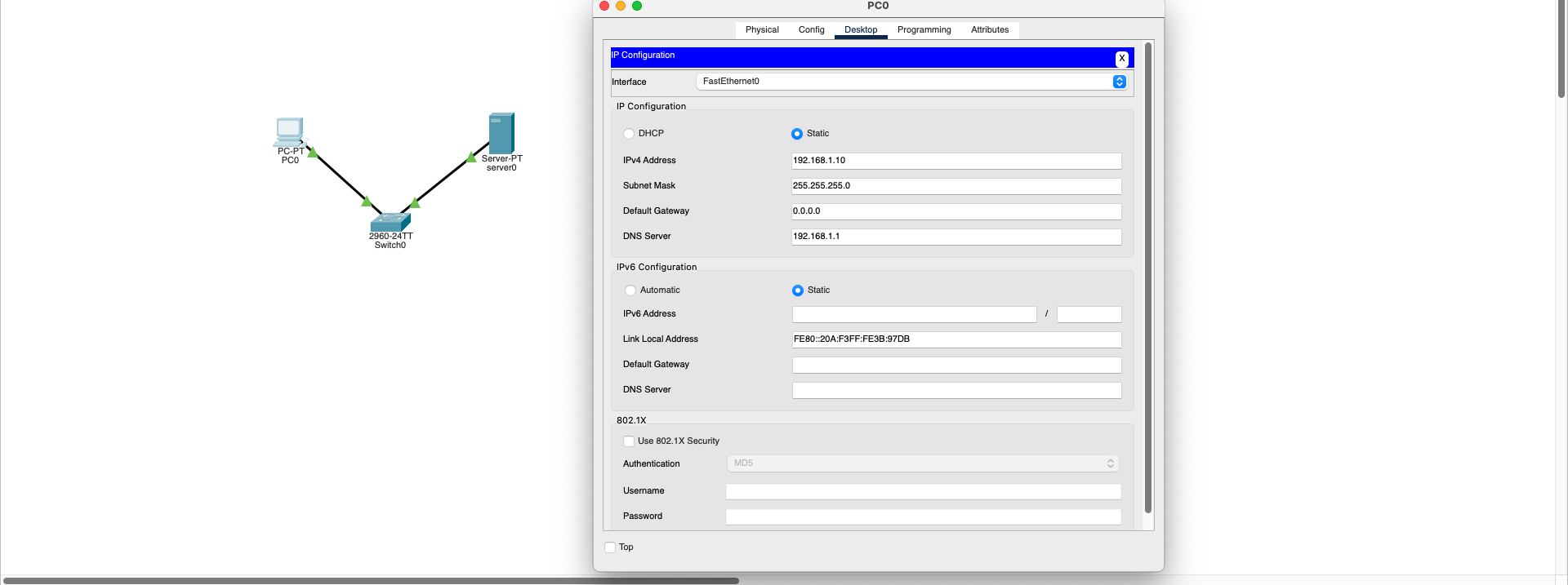
- The client device's DNS address should correctly match the DNS server's IP address
- DNS server must be configured and active
- A record for the desired domain name (e.g., www.gokay.com → 192.168.1.1) must be created on the DNS server
- If HTTP service is active on the server, the website will be accessible after DNS resolution
Result: With proper configurations, when the user enters a domain name, this name is translated to an IP address and the page opens successfully.
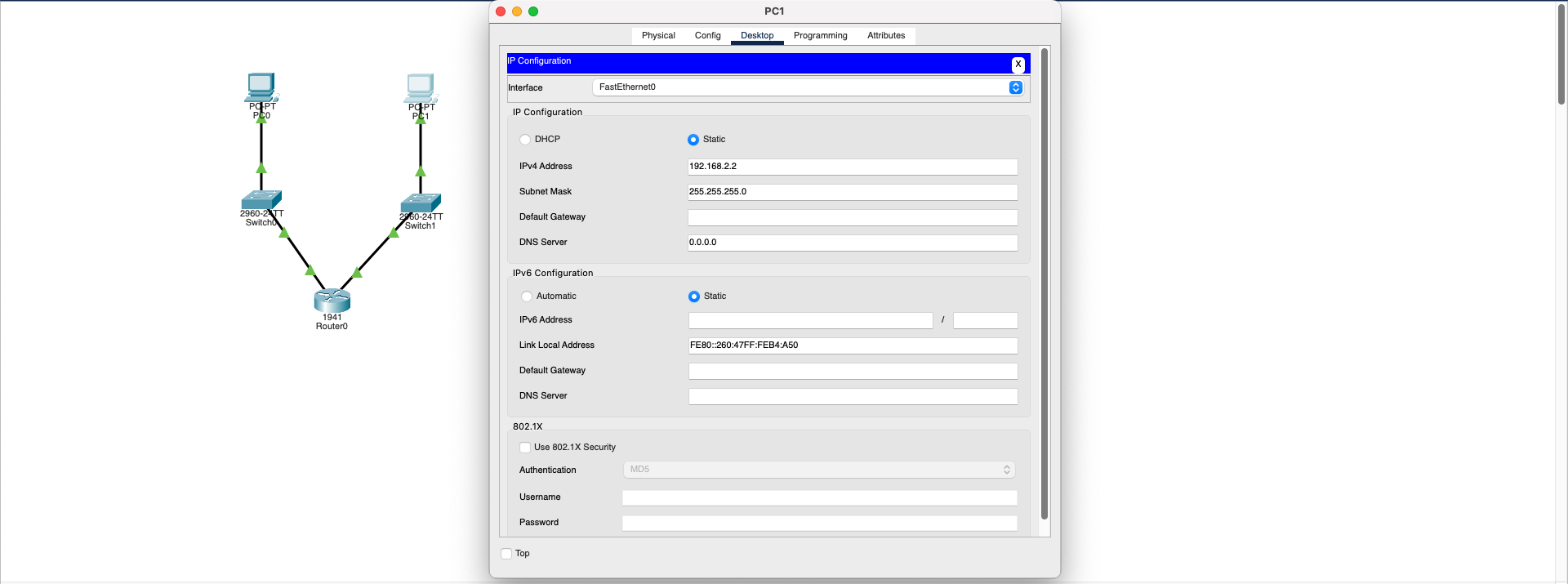
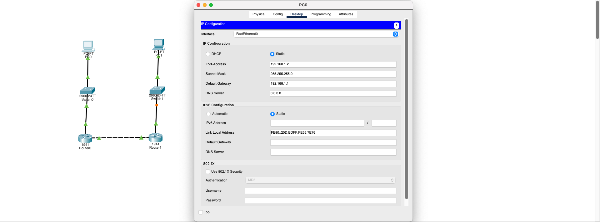
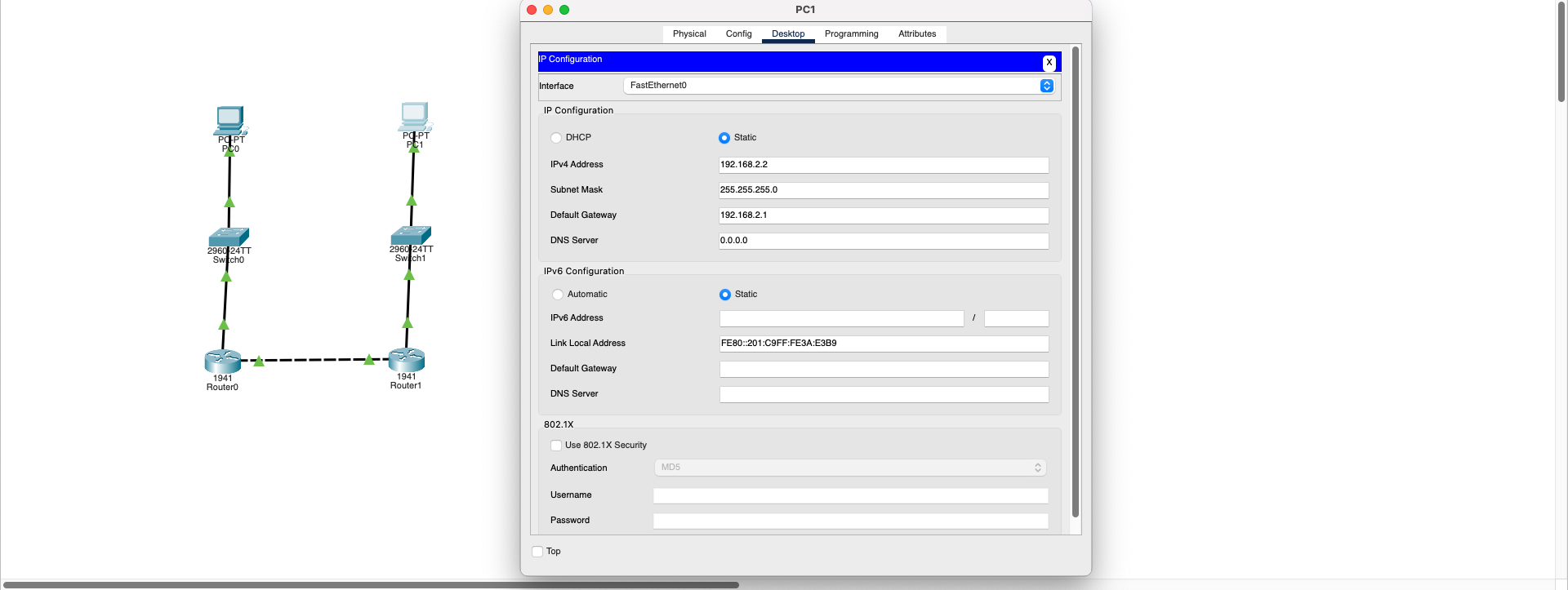
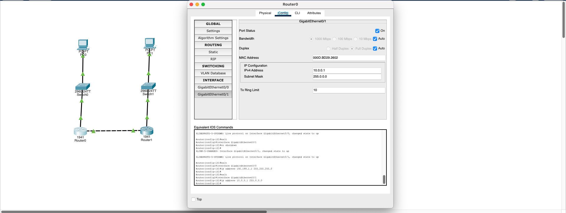
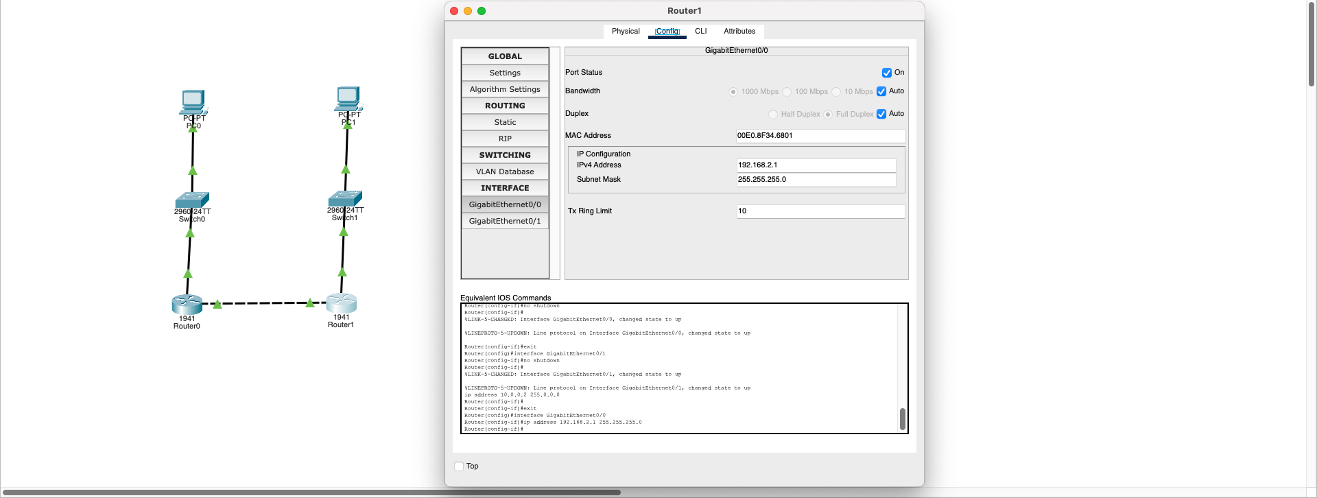
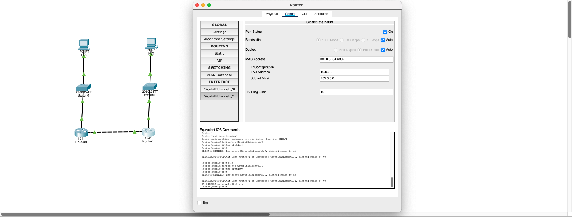
Download SimulationIP Routing Missing
Network Layer (L3)- PC0: 192.168.1.2/24 — connected router: Router0
- PC1: 192.168.2.2/24 — connected router: Router1
- Inter-router link: 10.0.0.0/24 network between Router0 ↔ Router1
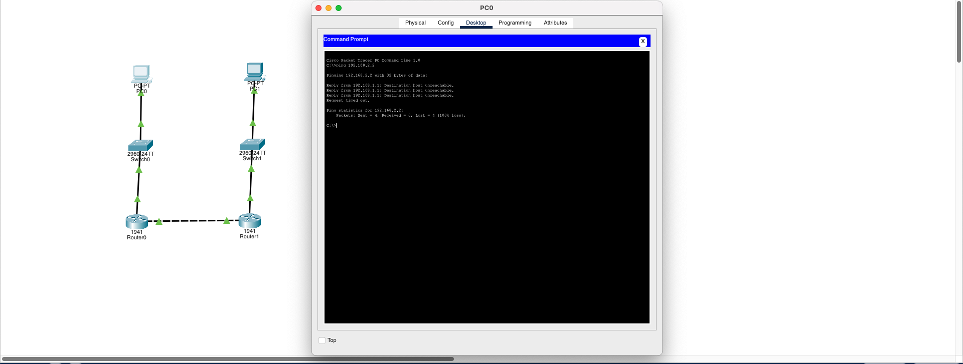
- Problem: Routers connected, IPs assigned but routing not configured
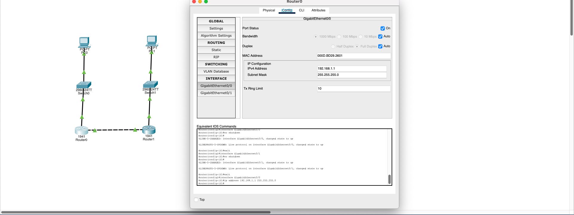
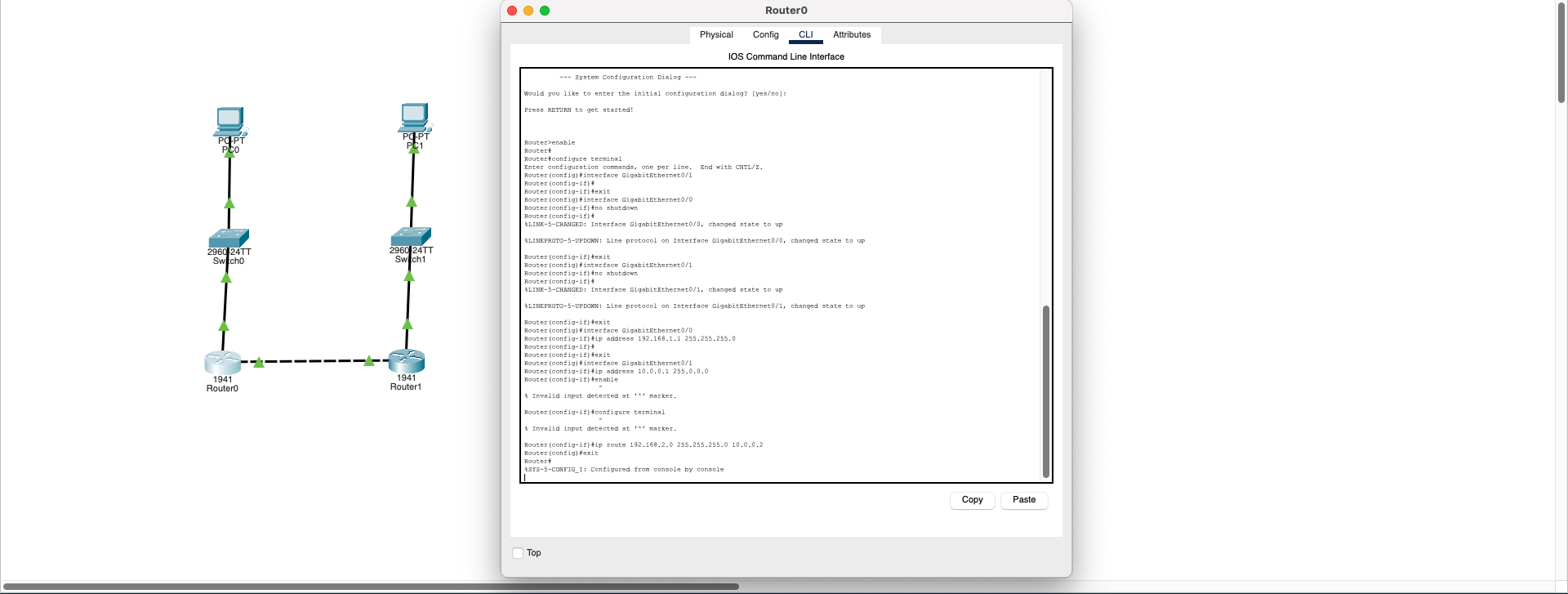
Static routing configuration should be applied to both routers to define routes to opposite networks:
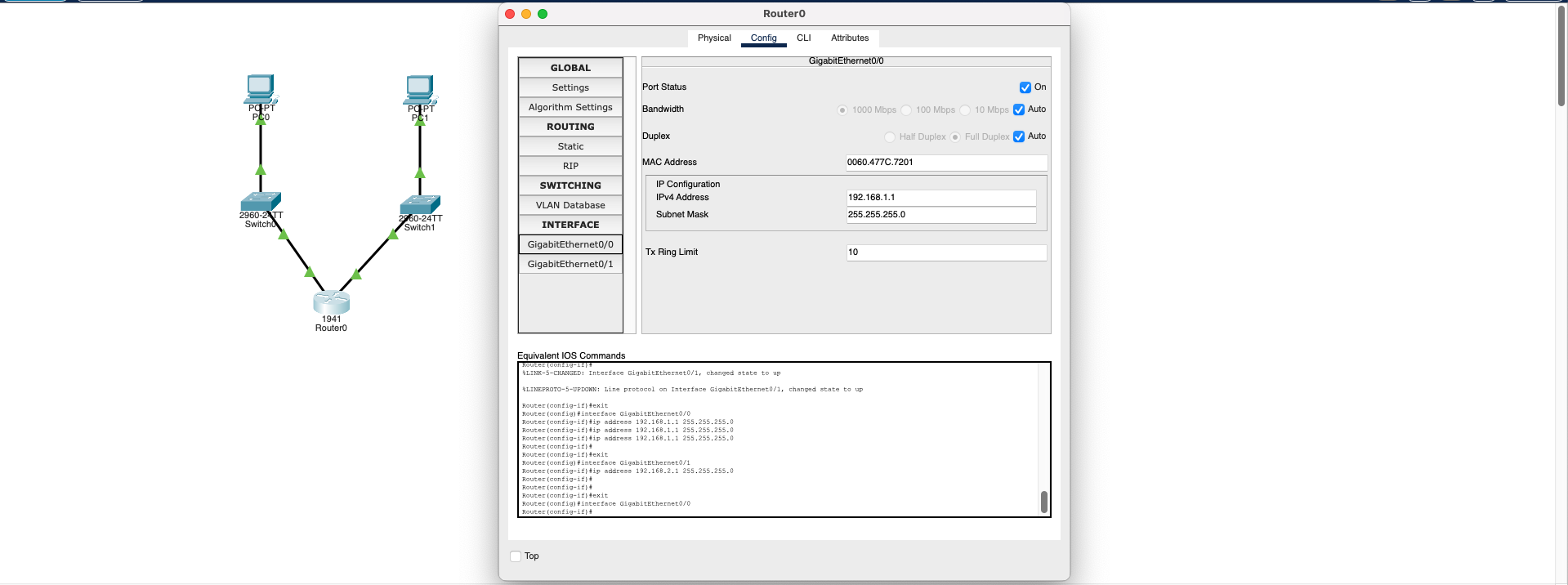
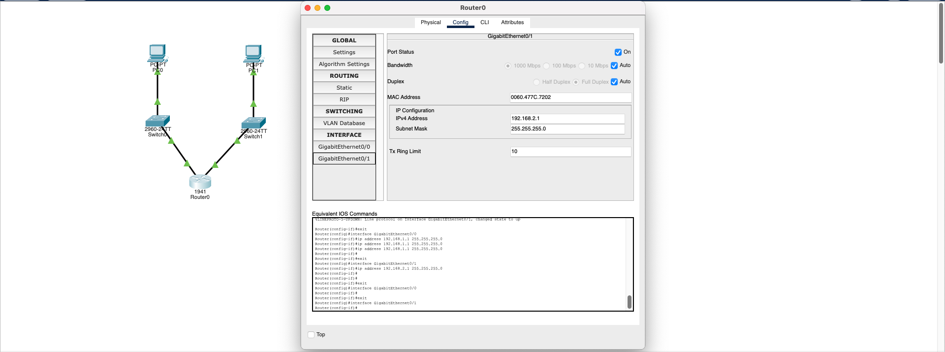
Router0 Configuration:
ip route 192.168.2.0 255.255.255.0 10.0.0.2
"To reach 192.168.2.0 network, use 10.0.0.2 (Router1) as next hop"
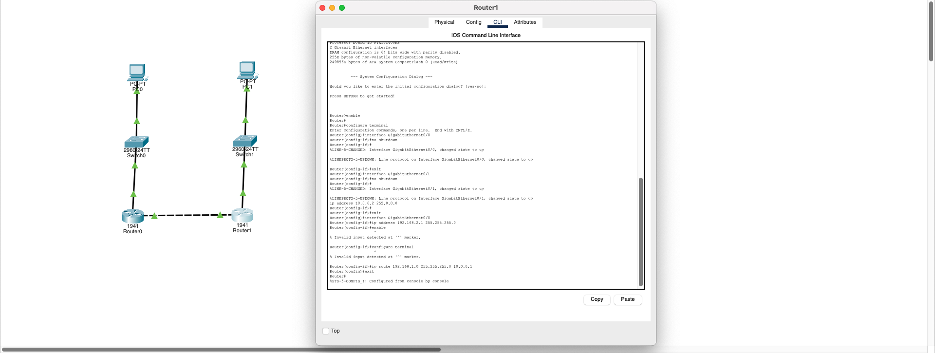
Router1 Configuration:
ip route 192.168.1.0 255.255.255.0 10.0.0.1
"To reach 192.168.1.0 network, use 10.0.0.1 (Router0) as next hop"
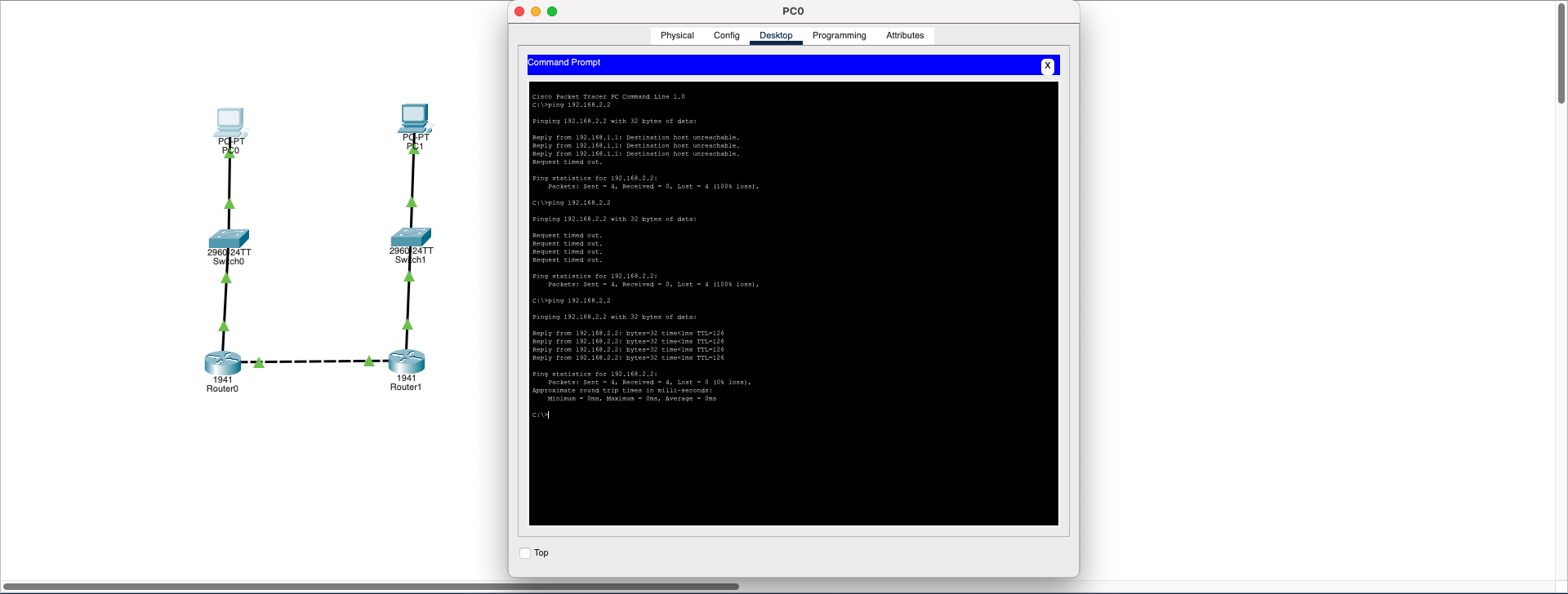
Result: After routing definitions are made, PC0 can ping PC1, two different networks communicate smoothly, and data packets find the correct route through IP routing.
Download SimulationDHCP Gateway Misconfiguration
Network Layer (L3)- IP Address: 192.168.1.x ✅
- Subnet Mask: 255.255.255.0 ✅
- Default Gateway: 192.168.10.1 ❌ (Unreachable IP!)
Therefore, clients can only access their own subnet but cannot reach the router and internet connection.
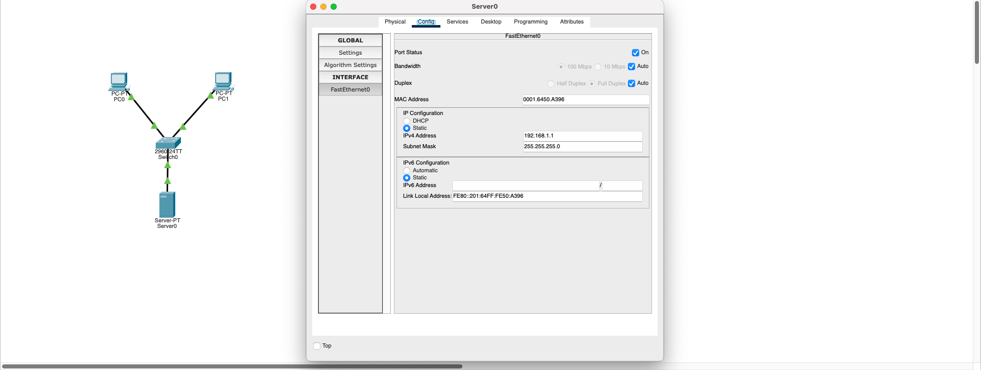
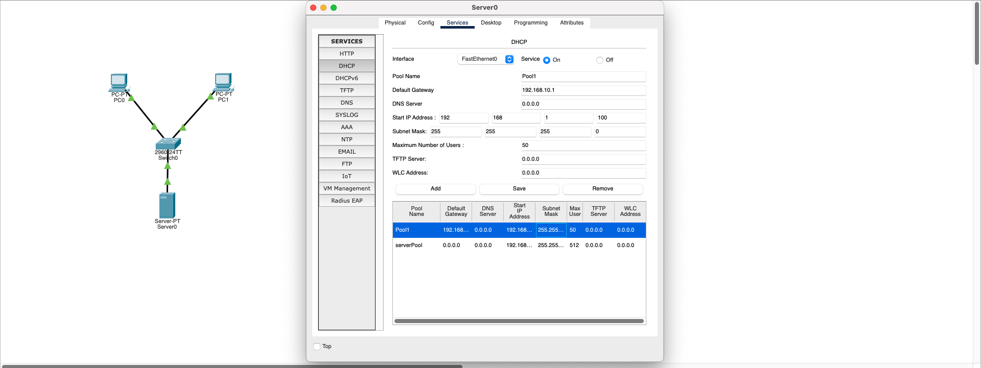
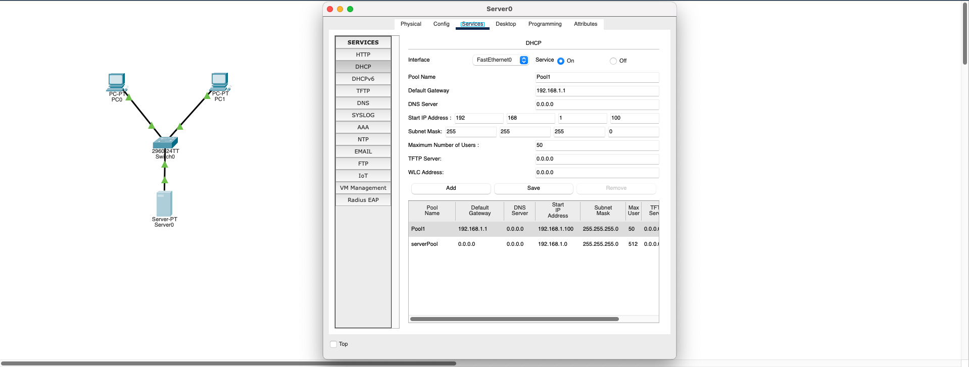
1. DHCP Server Configuration Fix:
- Go to Server0 → Services → DHCP section
- Check the existing Pool (e.g., Pool1) Default Gateway value
- Change incorrect IP (192.168.10.1) to correct gateway: 192.168.1.1
- Save settings with Save button
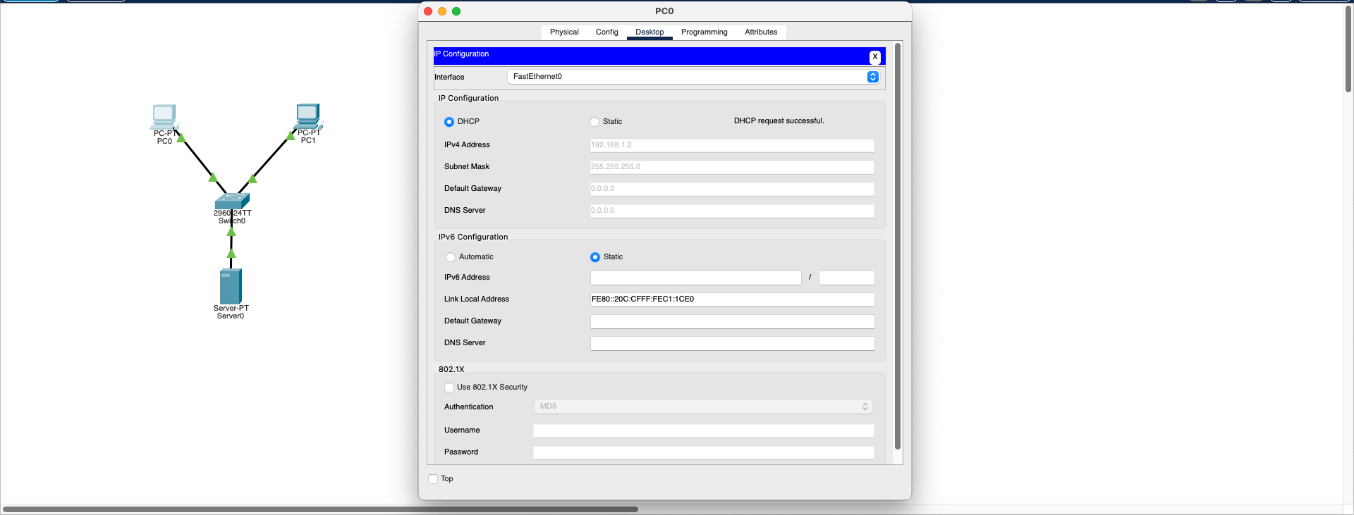
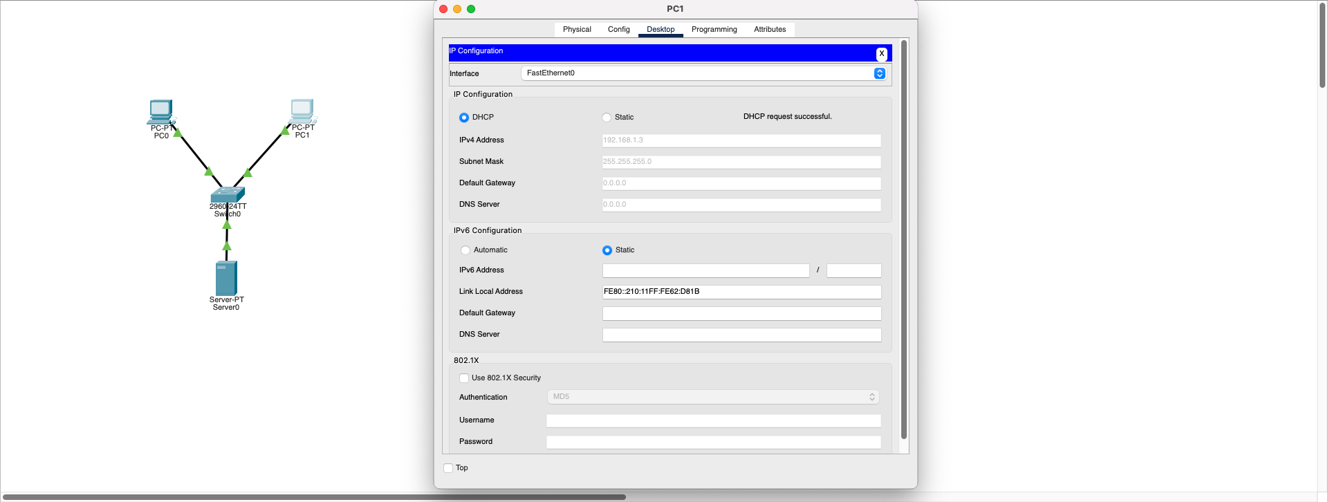
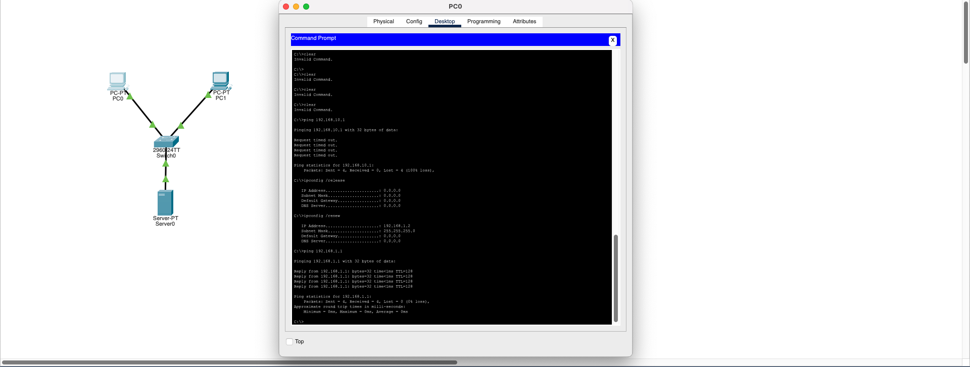
2. Client IP Renewal:
On PC0 or PC1 → Desktop → Command Prompt, enter these commands:
                             ipconfig /release

                             ipconfig /renew
These commands make the client release current IP and obtain new (correct gateway) DHCP configuration.
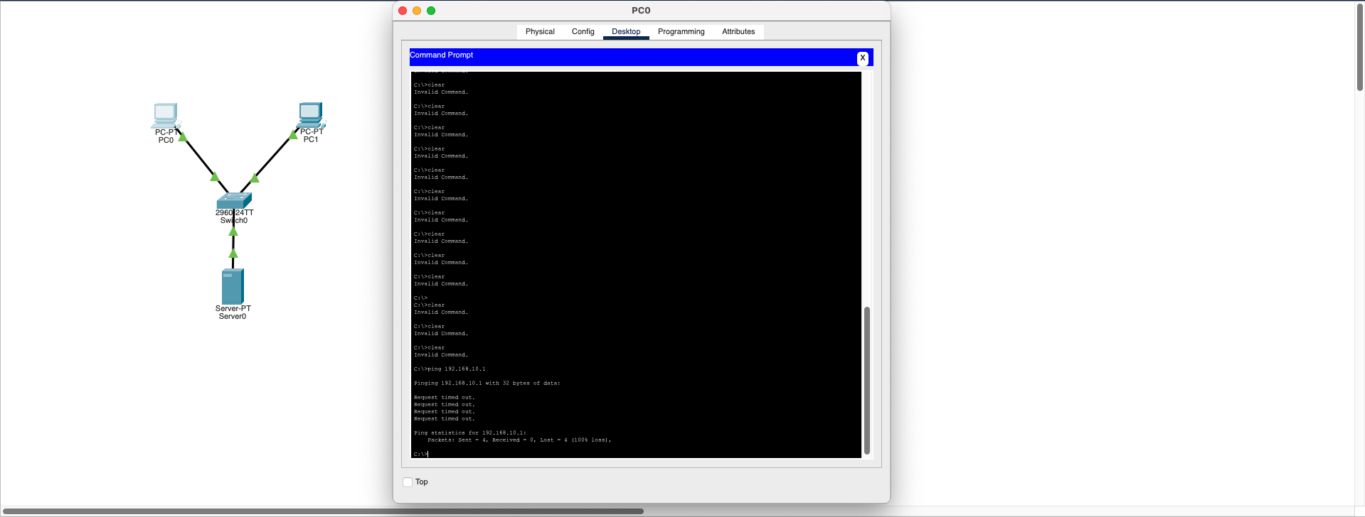
3. Connection Test:
After receiving new IP information, ping the router:
ping 192.168.1.1
✅ Now you will receive successful response instead of "Request Timed Out" error.
Result: This problem is caused by the incorrect Default Gateway address distributed from the DHCP server to clients. When the gateway address is correctly updated and clients renew their IP information, the connection problem is resolved.
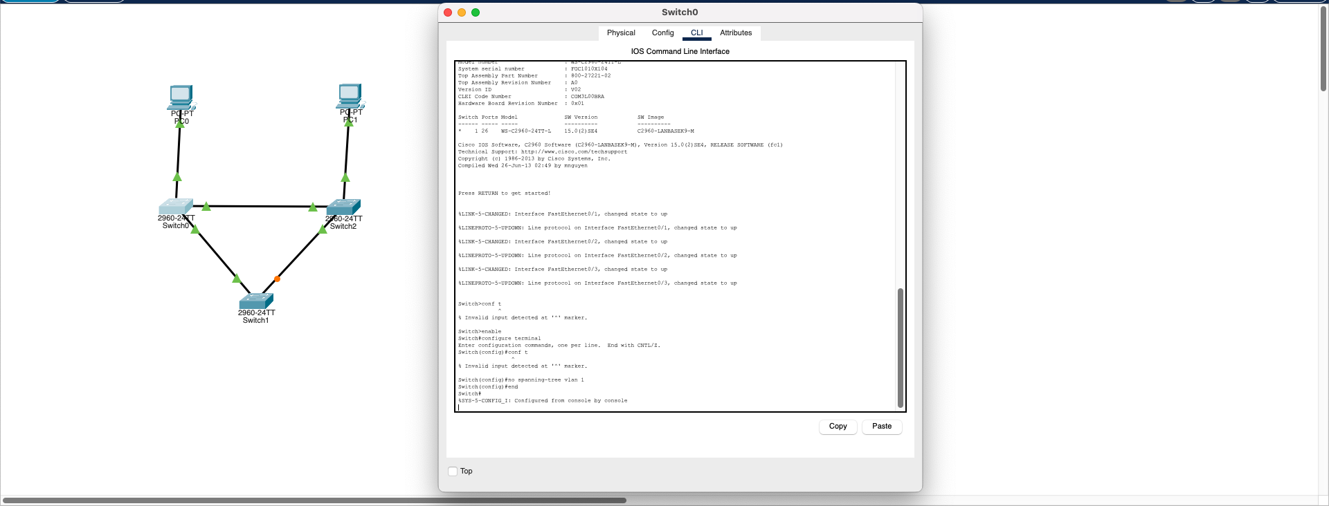
Download SimulationSwitching Loop (STP Disabled)
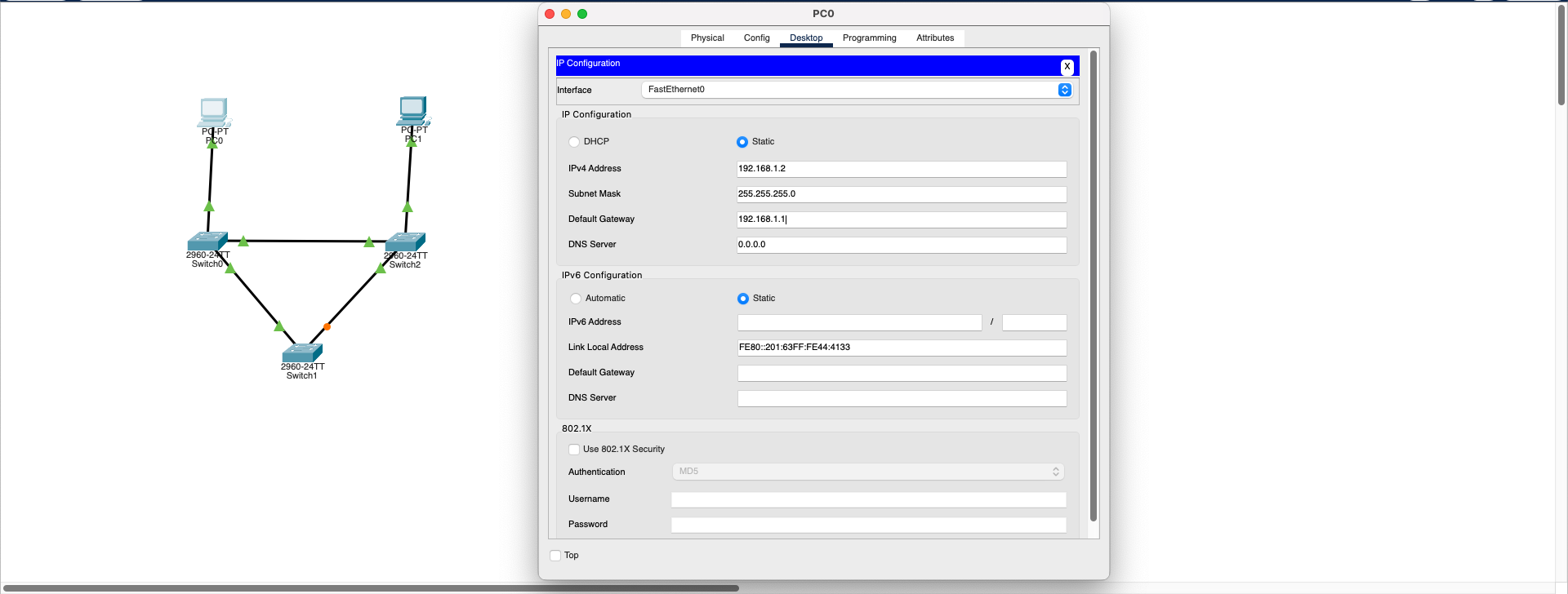
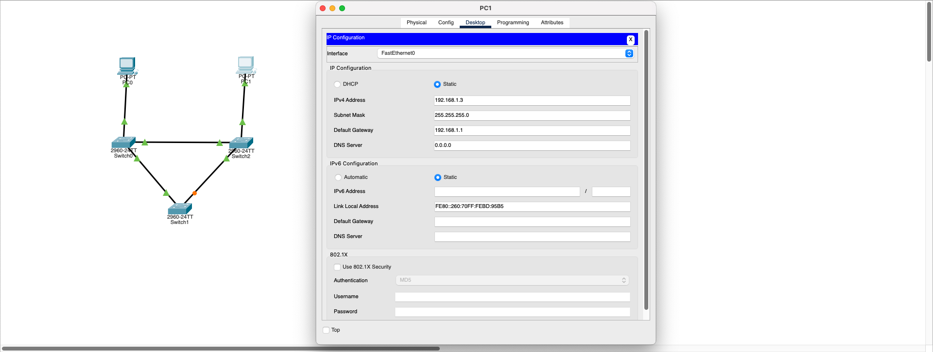
Data Link Layer (L2)- Topology: 3 Switches (Switch0, Switch1, Switch2) connected in triangular formation
- Endpoints: 2 PCs (PC0 and PC1) at the edge points
- Normal operation: One connection being orange (blocking) shows STP preventing loops
- Problem: When STP is disabled, all connections become active and network loop begins
Switching Loop Demo
PC0 ping timeout due to switching loop
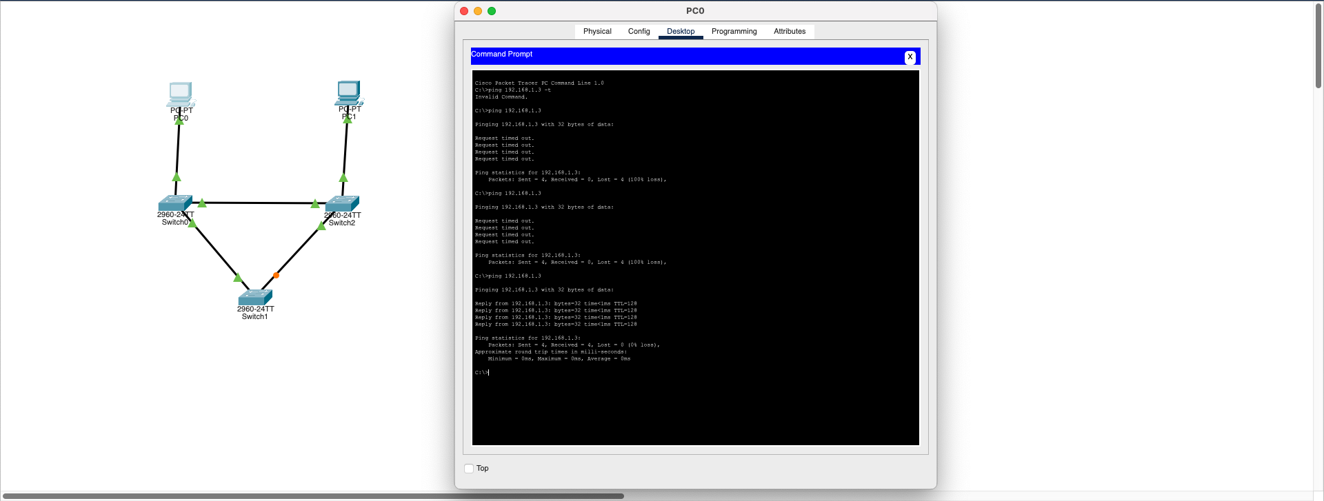
⚠️ Observed Symptoms:
- Ping requests in the network are delayed or unreachable
- Connection between PCs occasionally drops
- Unexpected slowdowns in network traffic
- Broadcast storm effects
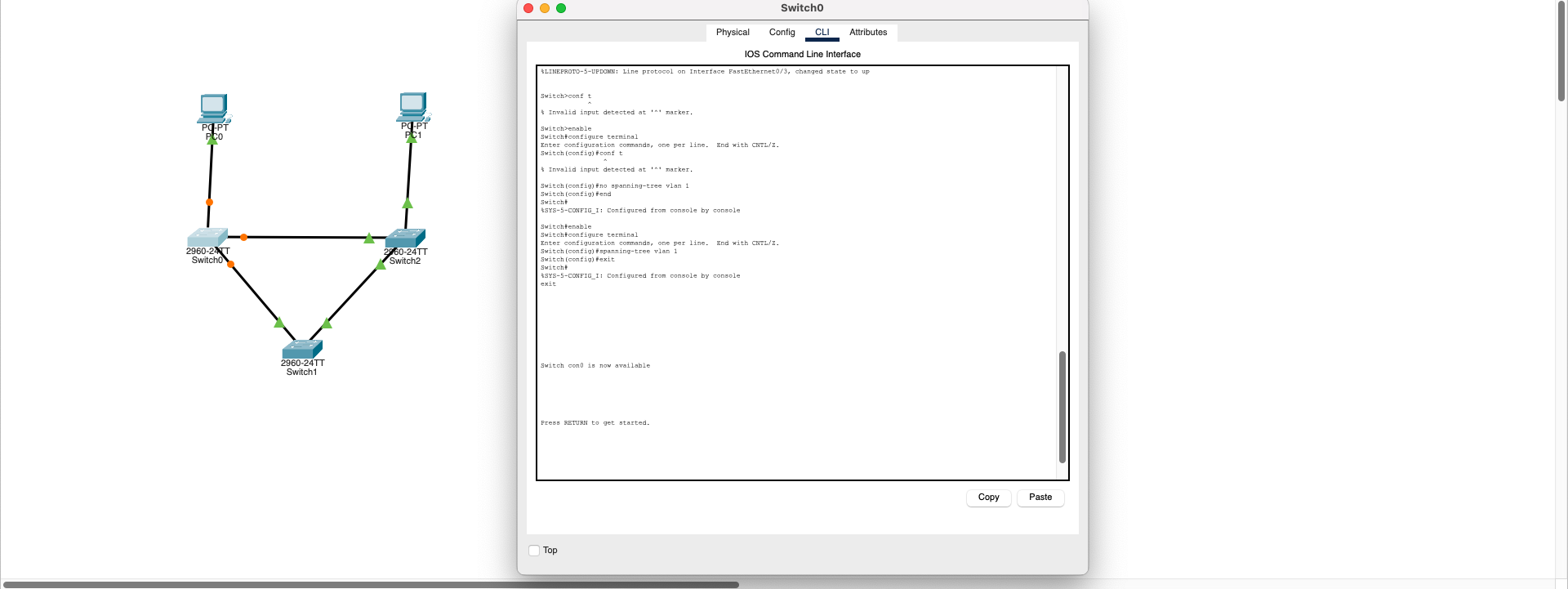
🔧 STP Configuration Steps:
Access each switch via CLI (command line) and enter:
                             Switch> enable

                             Switch# configure terminal

                             Switch(config)# spanning-tree vlan 1
This command manually enables STP on VLAN 1. When STP is active, one of the ports that could create a loop goes into blocking (orange) mode and prevents the loop.
Result: Spanning Tree Protocol (STP) provides network security and continuity at Layer 2 level. If STP is enabled, loops are automatically prevented in topologies created with multiple connections. If STP is disabled, switching loops can occur and this causes serious performance and security issues in real networks.
Download SimulationMTU Mismatch (Maximum Transmission Unit)
Data Link (L2) + Network Layer (L3)- Router A interface MTU: 1500 bytes
- Router B interface MTU: 1400 bytes
- Problem: If a device sends large packets with Don't Fragment (DF) bit set, packets cannot reach the destination
How to Observe the Problem:
- Ping command may work, but connection fails with large packets
- Testing with
ping -l 1472 -f 192.168.1.1returns "Packet needs to be fragmented but DF set" error
Real-World Examples:
- VPN tunnels
- MPLS or GRE tunnels
- ISP routing MTU limitations (e.g., 1492 or 1472)
🔧 Option 1: MTU Synchronization
Set the same MTU value (e.g., 1400) on all relevant interfaces:
                             Router(config)# interface GigabitEthernet0/0

                             Router(config-if)# mtu 1400
⚠️ Option 2: Disable Path MTU Discovery (Not Recommended)
Allow the device to fragment large packets (not secure, not recommended):
                             ping -l 1472 -f 192.168.1.1  ❌ (DF bit set)

                             ping -l 1472 192.168.1.1     ✅ (Fragmentation allowed)
🔧 Option 3: TCP MSS (Maximum Segment Size) Adjustment
Inform TCP-connecting devices about maximum segment size via router:
                             Router(config)# interface Gig0/0

                             Router(config-if)# ip tcp adjust-mss 1360
Result: MTU mismatch can cause data loss especially during L2 (frame) and L3 (packet) transitions. It's not noticeable with small packets like ping, but network problems occur during large data transmissions. Therefore, MTU values need to be carefully configured in tunnel structures or service provider transitions.
Note: This problem demonstrates the interaction between Layer 2 (Data Link - frame size limits) and Layer 3 (Network - packet fragmentation) of the OSI model.